Thursday, December 28, 2006

Reconstruction improvement

A Christmas of thesis writing is not what I would expect of a great Christmas, but still it was pretty nice! People were happy and having fun throughout the day, and there was only minor fighting (the stepfather can't go a day without sharing his arguments which have no basis in reality). In other words, a nice Christmas even though it was only a single day free from writing and coding...

I have come to terms with a basic failing in the application, which doesn't reconstruct nearly as well as it should. I believe I know two additions which could fix the algorithm, but with less than a week left, it's not realistic to believe in such a solution. The additions would be:
  • The addition of a point correspondence correction algorithm (by the original authors dubbed "the optimal solution"). This would correct clicked image points depending on epipolar constraints, which in turn would benefit the triangulation of 3D points.
  • Iteration in the algorithm. After reconstructing a set of 3D coordinates, these should be tested by projection back into the image frame - if the results of this re-projection are inaccurate, make a new estimate of the camera pose, which is then used for a new triangulation. After all, the first pose estimation is only done with four manually defined image points, and each point after that is also clicked manually, of course leading to a great deal of error in the reconstruction. Perhaps a similar iteration could be applied to the calculation of the fundamental matrix, the algebraic representation of epipolar geometry.
We decided on a temporary name for the application a few weeks ago. However, the name we chose - Pho2Model - is very similar to another product which has similar features - 'Photomodeler'. This leads to a need for another name if I/we should want to market it. Of course, this would require some corrections in the algorithm, but plans are ready for that, and it could be a nice side project after getting a 'normal job'.

Sunday, December 17, 2006

3D Reconstruction from photos and Image noise

For some reason, I had missed a basic step when creating my algorithm for 3D reconstruction from photos. The step, which I have been careful to consider in all similar previous projects, enforces an epipolar constraint and thereby "fixes" the problem of image noise.

The reconstruction done without enforcing this constraint is quite lousy, to say the least. Instead of searching through the software I created for errors (I've created quicker code, but not found any errors after using several methods of searching) I have decided to use 2-3 days for implementing a much more advanced algorithm, which enforces the epipolar constraint, and thereby "fixes" the problem of image noise...

If you're interested, an article named "Triangulation" from Hartley and Sturm, published in 1997 (sorry if any detail is wrong, no ill intention).

Hope this post helps you,
E.Hunefalk [First name not included because of spam risk - with some luck my thesis will published in 2007 though, so the name shouldn't be difficult to find :-)]

Saturday, October 21, 2006

Side project - Rhino3D Stadium modelling

I just started a small side project, to relax from the programming with some 3D modelling - even though I'm programming a 3D modeller. Does that sound weird? Well, I can live with that...

The first image to the right is what the model looks like after a days work. I base it on images from Stadionwelt.de and measurements from the city archives. The stadium is called Olympia, and stands in the city of Helsingborg, Sweden. I've been looking a bit on a couple of tutorials for the conversion of the stadium into games such as FIFA 07 and PES. The process of building the stadium is pretty straight forward, simply using surfaces to create one small part at a time. This way, I created a single part of the South Stands of the stadium and then copied it to be the same size as the pitch width (second image, on the left side).

From this, it was easy to change the textures (which were originally applied by simply selecting a quad and setting the basic material texture to whichever image was needed for that piece) and get the result on the next image. Before rendering that image, I also substituted a couple of ad screens for a big screen where re-runs and video from other matches are shown.

The arena has two standing short sides, while the long sides are seated. The short sides basically look the same, while the long sides have very different features from eachother. The stadium is seen as Swedens most beautiful, but will be rebuilt to accomodate more people in a few years.


Wednesday, October 11, 2006

Modelling application

So I've been working on a modelling application in its simplest sense...

The shortest summary I've been able to create works as follows [extreme draft, but comments are still welcome]:

Modelling

The modelling section of the application consists of three subparts. These are called Pre-modelling, Parameter Value Generation and Post-modelling. In short, the system lets a user create models from his or her perception of the object of interest, followed by the step where images are used to find distances between different coordinates in the object and finally the user goes into the post-modelling part of the system, to correct possible mistakes made in the previous parts of the process.

Pre-modelling

Here, a user can specify how a building, or object (hereafter all specified as buildings), is put together. This is done by fitting different ‘blocks’ together, where a block could for example be a cube to model the base of the building or a pyramid for the roof. In this part, a user can specify parameter constraints, both in the same block and between different block. For example, the height is often the same at the four corners of a house, while the roof is aligned in all four directions of a square building, and also has its bottom at the top of the base.

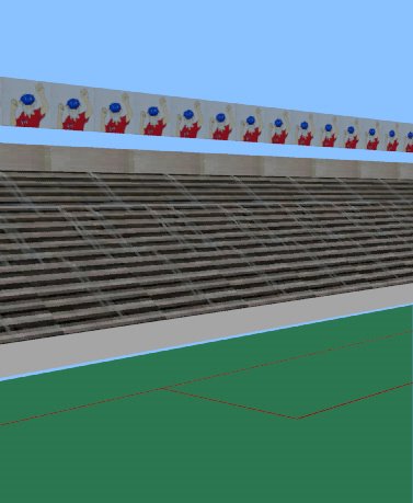
The camera can be moved to fit background images, or the user can simply model on-the-fly.

Generating World Coordinate Values

In this part of the process, the user specifies 2D image coordinates – most often in photos – which correspond to 3D world coordinates for the final model. This is the most work intensive part of the process, and consists of three steps:

1) Find the Fundamental matrix (F) between images. By clicking on at least seven corresponding points the minimal solution, RANSAC or the eight-point algorithm can be used. Together with the cameras intrinsic parameters K and K’ the Essential matrix (E) can then be found. Through SVD the camera rotation and translation are derived.

2) For each point correspondence compute/triangulate the corresponding 3D space coordinate X that project to those image points. Initialize structure from two views. For each new image/image pair:

a. Determine pose

b. Refine current values (see more on point 3)

c. Extend structure

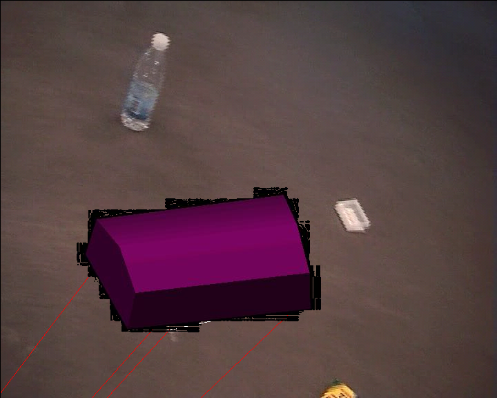
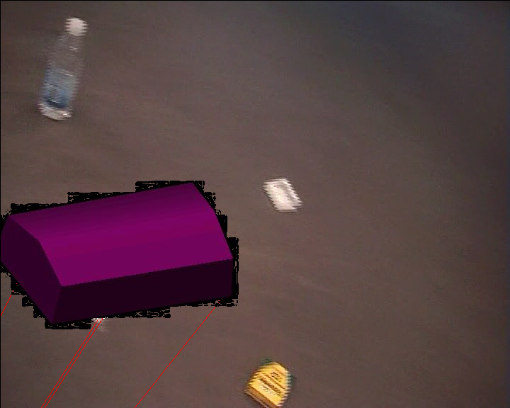
3) Weigh points depending on angle compared to camera – Better angle (width etc.) when straight forward than at narrow angle. All surfaces are two dimensional, and should be evaluated as such before moving to the third dimension. Pick corners in post-modelling stage by putting boxes (primitives) at each vertex. When vertices are the same for multiple surfaces, only use one box (which can be picked to change values).

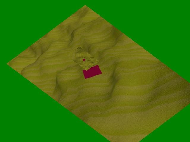
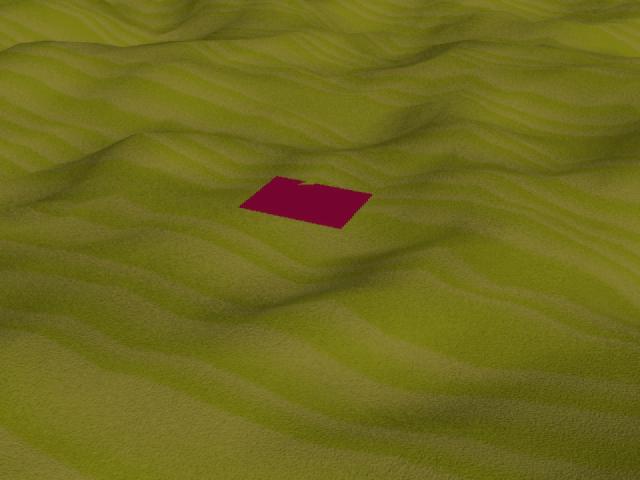
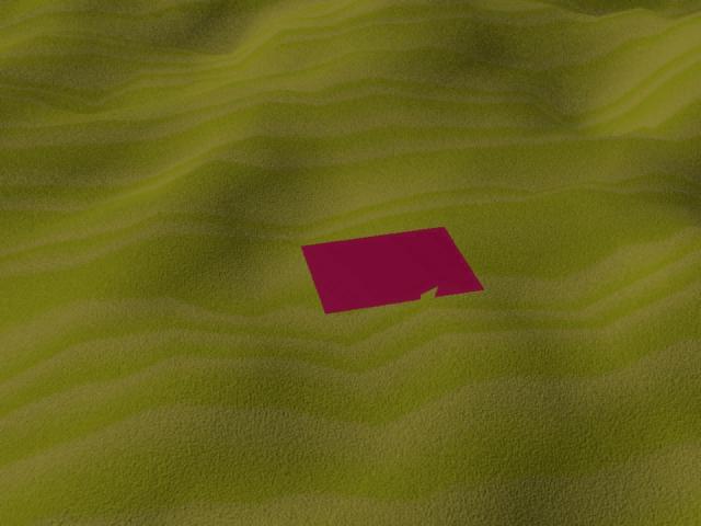
4) Move coordinates to set one model corner at world origin (must stand on ground, with one corner at (0,0,0)). Show with a ground plane, and let user change coordinates. This way, we’ll align this corner with the tracked points from a video stream, where one corner should be set to (0,0,0) and the width/length of the tracked square should be set to the width/length of the modelled building.

5) Save mesh: Save the model as x-file, move texture images to assigned folder together with ".x"-files

With all these parameters, the application calculates 3D world coordinates depending on which coordinates have been specified from images, which different parameters should have the same value and if one or other value is unlikely for the world coordinate.

Post-modelling

This part is very similar to the pre-modelling. Here, the user can look at the values given from the second step of the modelling process, and for example change single values (such as block height or width) or set new alignments if an error is found. From this step, it is also possible to go back to the second step of the modelling process, to refine the measurements or even add new parts of the building. This way, the user can create one part of the building at a time, if details are needed. Also, a rougher initial model can be created to see an early sample of the building.

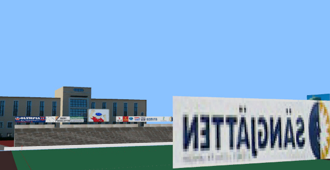
The post-modelling part of the system lets the user set the camera to the transformation used in specified images, which can then be used as background to a wireframe version of the model.

Texturing

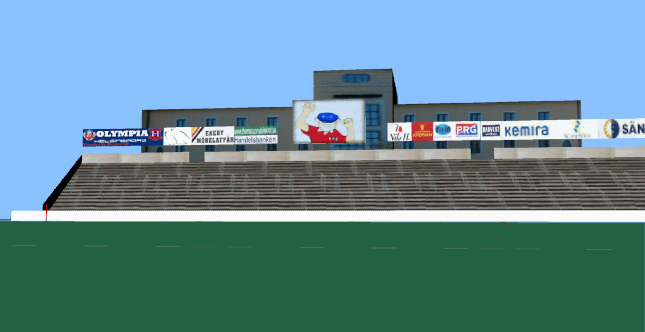
The texturing process from the users point works by finding corners of the surfaces which are wanted as texture images. After specifying the same four corners in a number of images (1-N), the user lets the application work in the following way:

For each texture image pixel (x,y) coordinate:

  • Use the specified corners and specified texture size to calculate the homography from image to texture.
  1. Use the homography to find the pixel colour value (0-255) in image i, and put the value in a histogram together with all corresponding coordinates from the specified images.
  2. Find the histogram bin with the highest occurrence, and use this to set the textures corresponding pixel colour value.
  3. If the resulting texture image gives an unsatisfactory result, remove or add more images and go back to step one. The result might be unsatisfactory due to for example partial occlusion, image artefacts (if using too few images), pixelated regions (due to perspective distortion in the original image, or the texture size being too small comparing to how close the camera gets to the finished model) or a too blurry image.

Thursday, August 31, 2006

Texture creation from multiple photos

When creating a 3D model from photos, you of course want some textures for the walls etc. However, when taking photos of the building you wish to model, some parts of the buildings may be occluded buy other objects, such as trees, cars or other buildings. If this is the case from all angles you take the photos from, you'll probably want to get rid of the occluding objects when creating the textures, so you only get the pixels which are actually showing the wall. One option, which I wouldn't recommend, is to take the average colour values showing the wall. Another option could be to detect the occluding object, and not use those pixels when taking pixel values from that particular view. The method used in my project was the following:
  • Get the homographies between different views from point correspondences - where the simplest method uses four clicks in the corners of the wanted texture. Using only four point might give a lower accuracy on the homography, but gives good enough results for an architectural scene, where you don't go too close to the buildings.
  • For each pixel in the wanted texture:
    1. Find corresponding coordinate in in each clicked image (using the homographies).
    2. Put the pixel values for the coordinate in a histogram.
    3. Find the maximum occurence value in the histogram, thereby determining the value of the texture coordinate.

Reconstruction plans

Today I'm really sick, so I decided to stay home and start programming some of the ideas I've gotten from all my studying the last two weeks.

I'll start by creating an interface where people can click on two photos, to use corresponding points for reconstructing a building. In the background, I'll be using some of the stuff I mentioned in the previous post, to find the movements of the camera.

To find the camera position and rotation, I'll be using RANSAC or the 8-point algorithm to get the Fundamental Matrix (F), and then use the Intrinsic camera parameters to get the Essential matrix (E). From this, the rotation and translation of the cameras will be derived.

The reconstruction of 3D points depends on prior scene and camera knowledge. If the camera parameters hadn't been known from calibration, the reconstruction could only be known up to an unknown projective transformation of the environment. The intrinsic parameters gives us the possibility to reconstruct up to an unknown scaling factor, while an unambiguous reconstruction can be done if both intrinsic and extrinsic are known (for example if you have architectural plans available).

In the situation with calibrated cameras, but unknown scene parameters (such as 3D point locations, scale, rotation etc.), we don't know the baseline of the system and can therefore not recover the true scale of the viewed scene. If we know the distance between two points in the scene, we can at least recover the scaling factor to which the reconstruction is unique.

Wednesday, August 30, 2006

3D Reconstruction from Photos

Something I thought would be a simple problem turned out not to be - but mostly because of my own clumsyness. I just noticed a function in OpenCV that I could've used instead of spending time on programming it myself.

I found that through OpenCV, I can use the fundamental matrix - retrieved from at least seven point matches in two photos - and take the SVD (Singular Value Decomposition) on that as a step to find rotation and translation of points in the photos. Since I didn't at first find the SVD in OpenCV, I clumsily assumed that it wasn't in the library. After a day, I accidentaly came across it, but in what seems to be a slower version - cvmSVD() - instead of what I just found, the cvSVD() function :-)

I'll now find the fundamental matrix from point matches, use the internal camera parameters to normalize it into the Essential Matrix, and then use SVD to find the rotation and translation...

We'll see how it works - at least it gave me hope to be done in two weeks, like I had planned to from start :-)

Monday, July 03, 2006

Requested: Video texture in MDX

I got a request for some code using the TextureReadyToRender with video surfaces in MDX. The following works, but there's a problem with disposing the video texture after the vido ends. I've seen a solution or two, but since the approach with video surfaces won't work for my project, I decided to not implement that part for now. Maybe I'll do it later, just to satisfy my curiosity :)


#region Groundplane with video texture
protected VertexBuffer CreateVertexBuffer(Device dev)
{
try
{
video = Video.FromFile("test.avi");//videoTexPath
//video.Ending += new EventHandler(MovieOver); // TODO: DISPOSING DOESN'T WORK!!
video.TextureReadyToRender += new TextureRenderEventHandler(onTextureReadyToRender);
video.RenderToTexture(dev);
video.Play();

// vidFrame.Text = Convert.ToString(video.CurrentPosition);
vidLength.Text = Convert.ToString(video.Duration);
//rotX.Text = Convert.ToString(video.CurrentPosition);
}
catch (Exception err)
{
MessageBox.Show(err.ToString());
}

CustomVertex.PositionTextured[] quad = new CustomVertex.PositionTextured[4];
quad[0] = new CustomVertex.PositionTextured(-300.0f, -300.0f, 0.0f, 0.0f, 0.0f);
quad[1] = new CustomVertex.PositionTextured(-300.0f, 300.0f, 0.0f, 0.0f, 1.0f);
quad[2] = new CustomVertex.PositionTextured(300.0f, -300.0f, 0.0f, 1.0f, 0.0f);
quad[3] = new CustomVertex.PositionTextured(300.0f, 300.0f, 0.0f, 1.0f, 1.0f);

VertexBuffer buf = new VertexBuffer(
typeof(CustomVertex.PositionTextured), // What type of vertices
4, // How many
dev, // The device
0, // Default usage
CustomVertex.PositionTextured.Format, // Vertex format
Pool.Default); // Default pooling

GraphicsStream stm = buf.Lock(0, 0, 0);
stm.Write(quad);

buf.Unlock();
return buf;
}

///
/// The onTextureReadyToRender method (called from TextureRenderEventHandler to handle videotexture)
///

protected void onTextureReadyToRender(object sender, TextureRenderEventArgs e)
{
if (e.Texture == null)
return;

SurfaceDescription ds = e.Texture.GetLevelDescription(0);

if (ds.Pool == Pool.Default)
{
sysSurf = _device.CreateOffscreenPlainSurface(ds.Width, ds.Height,
ds.Format, Pool.SystemMemory);
}

using (Surface vidSurf = e.Texture.GetSurfaceLevel(0))
{
if (_tex == null)
{
_tex = new Texture(_device, ds.Width, ds.Height,
1, Usage.Dynamic, ds.Format, ds.Pool);
}
using (Surface texSurf = _tex.GetSurfaceLevel(0))
{
//_device.GetRenderTargetData(vidSurf, sysSurf);
//_device.UpdateSurface(sysSurf, texSurf);
SurfaceLoader.FromSurface(texSurf, vidSurf, Filter.Linear, unchecked((int)0xffffffff));
}
}
Invalidate();
}

///
/// Movie playback has ended
///

/*
void MovieOver(object sender, EventArgs e)
{
Dispose();
}
*/
#endregion


I've tried the following for disposing (cluttered with disposing some other textures):
protected void DisposeTextures()
{
if (_textures == null)
{
return;
}
foreach (Texture t in _textures)
{
if (t != null)
{
t.Dispose();
}
}

if (_tex == null)
{
return;
}
else
{
_tex.Dispose();
_tex = null;
}
if (video != null)
{

if (!video.Audio.Disposed)
{
video.Audio.Dispose();
}
if (!video.Disposed)
{
video.Stop();
//video.Dispose();
video = null;
}
}

}


I'll update here if I find a link where disposal of the video is explained, I should have one somewhere... From what I remember it doesn't work with only managed directx though, so you'll have to do some other tweak ;)

Tuesday, May 16, 2006

Augmented Reality

I've had some progress this past week. Different parts of the application were put together, giving a result where you can put a 3D model on top of an object (or on the ground, a wall etc.) in a background image.


The house/box was made in 3Ds Max, and is of course supposed to have the same orientation as the ground in the background, and look like it's placed on top of four dots on the ground, with appropriate size. The red lines below the box/house are supposed to continue in the same directions as the house wall corners - which they are obviously not, even though close for now. The red lines in the image under the house/box are supposed to go from the house corners to the third vanishing point - meaning that the house is a bit off, but not extreme. I'm guessing that it has something to do with the intrinsic camera parameter estimation, but I also know that there's some problems with making those parameters fit with Managed DirectX, since they are not of the same type....

I basically started again from nothing at the start of last week, worked 6-10 hours a day and came up with this. It's great progress for just a week. This week I'll make a new part of the program, after "resting" from it (actually doing my study job) for two days. The new part will be a camera calibrator, where a user can click a few times on an image, write some measurements, and then get the camera parameters for it.

Sunday, May 07, 2006

OpenCV stuff

I've started learning how to use OpenCV over the last few days. That's the Open Source Computer Vision Library. While learning some of it, I've been using my thesis partners code to get my hands dirty a bit faster. The problem with this approach is of course that you don't have full control of all parts, and there's always something there to supprise you. At the same time, when you're trying to avoid unpleasant suprises, you might end up making a mistake because of that. So I just spent 1-2 hours trying to figure out why nothing was drawn in the images/frames in the video. The fix: put the line-drawing before rendering the frame ;)

What I'll be doing this week is something like the following
  1. Calculate and draw the normals in the corners of the tracked building. Here I'll use the camera calibration matrix K together with the vanishing line (the "horizon") to find the third vanishing point.
  2. Calculate extrinsic parameters (position and orientation) in 4-5 frames, using the tracked building corners.

Thursday, April 13, 2006

Chosen First design method - Videotracking and mesh insertion

Just to clarify how the application is supposed to work, I'll give a summary here.

First, in my thesis partners part, coordinates in a video are chosen. This coordinates should at this early stage be the four corners of where a building should be inserted upon. Coordinates are found in a few frames, clicked on, and then the application interpolates between the frames. This is sometimes called keyframing.

My part of the application takes the four coordinates for the current frame, creates a homography matrix (used for calculating coordinate correspondence between different coordinate systems) and uses the homography to:
  1. Set texture coordinates for the ground plane - basically calculating the corner coordinates and then normalizing them.
  2. Find the position of where the house should be inserted on top of the ground plane.
  3. Find the rotation of the house, through the recieved four coordinates.
This sounds very simple in some ways, but there are some stumbling blocks - as has been described in previous posts. Currently, the greatest obstacle is that the video texture doesn't dispose - but I expect to have that solved within a few days (I'm also working on other stuff parallell, I'm not that slow ;p).

I expect to later move a lot of the calculations to HLSL, hopefully making it faster in the process. But for now I've decided to stick to the simplest ways of doing things and just make them work...


If we have time for the second method, it will be different in a number of ways. In that method we wont use any video in the 3D world, but instead only calculate which position and orientation to put the inserted building. While in the first method we can consider the building only being rotated around the Y-axis (meaning the building is always having the same sides facing up/down, but "changing other directions"), the second method also considers the other axises, making us calculate orientation and position in X, Y and Z coordinates. As a comparison, the first method calculates the position in X and Z coordinates, and as mentioned the rotation is only around the Y axis.

Wednesday, April 12, 2006

MDX Video texture code

Since I've found that a lot of people have had trouble with creating video textures with Managed DirectX, I decided to post some of the code for it here. The code basically loads the video and then renders when the current frame has been copied.

The following can be put for example where you create the mesh, as I did - or of course where ever else you find suitable:
video = Video.FromFile("test.avi"); //I'll set this to open a video with the file menu later
video.TextureReadyToRender += new TextureRenderEventHandler(onTextureReadyToRender); //Set an event handler to fire when the texture is ready to render.
video.RenderToTexture(_device); // Render the texture with the device (graphics card)
video.Play();
About an hour after writing the post it's time to update it.... I changed some stuff in the eventhandler, giving the following code as result:
public void onTextureReadyToRender(object sender, TextureRenderEventArgs e)
{

if (e.Texture == null)//If there's no texture file (video) for 'e', then get out of here
return;
SurfaceDescription ds = e.Texture.GetLevelDescription(0);
if (ds.Pool == Pool.Default)
{
sysSurf = _device.CreateOffscreenPlainSurface(ds.Width, ds.Height,
ds.Format, Pool.SystemMemory);
}
using (Surface vidSurf = e.Texture.GetSurfaceLevel(0))
{
if (_tex == null)//If there is no texture set to "_tex"
{
_tex = new Texture(_device, ds.Width, ds.Height,
1, Usage.Dynamic, ds.Format, ds.Pool);
}
using (Surface texSurf = _tex.GetSurfaceLevel(0))
{
SurfaceLoader.FromSurface(texSurf, vidSurf, Filter.Linear, unchecked((int)0xffffffff));
}
}
Invalidate();
}

To give some quick comments:
  • The update peoblem (application not updating without user interaction) was fixed when I put in the Invalidate() method.
  • The updating looks quicker than before - but of course it's impossible to tell by the naked eye.
  • The changes were made after I found some useful things in the book("Managed DirectX 9 Kick Start" by Tom Miller in the MDX team)
I believe most is pretty obvious. Just get the video file, check when it's loaded and ready to render, render it to a texture and watch the result...

Sorry about the lack of indents in the code - Blogger doesn't like the easy methods to create indents like tab/space, so I'll just skip that unless I get comments about it ;-)

I still have a lot of trouble with disposing the video texture when closing the application, but since I can't find anything to fix it after trying different ways and searching different places, I'll leave it for now...

The next things I'll do will just be minor issues. like for example stretching the video texture different ways, just to see the effect of it, and if it can be used easy and quick to rectify the frame images..

Tuesday, April 11, 2006

Video perspective distortion rectification

Well... the title says it all - need I say more?

This Thursday - two days away - I need to have the next step of the MDX application ready!! This means, at least, the following substeps, since my last post:
  • Creating a ground plane (a quad in Managed DirectX), which uses a video as texture. This substep was finished today, after a lot of trouble - mostly because there's next to no information about video textures with Managed DirectX. I almost gave up and changed to OpenGL, but since I want to learn as much MDX as possible I let it take the time it took.
  • Creating a new house mesh, which has the same size (at least proportions) as the place in the video, and a texture of its own.
  • Finding the homography (coordinate correspondences) between "real world coordinates" and the current frame in the video texture. This means calculating a new homography matrix for each frame, which of course may slow down the application. This can hopefully later be moved to HLSL instead, to let the graphics hardware take care of it whichever way it likes.
  • Setting texture coordinates of ground plane, according to the homography matrix.
  • Setting location and orientation of the house mesh, according to coordinates from the video texture, combined with the homography. However, the coordinates come from clicks in my thesis partners application, meaning I'll have to wait for those before doing anything final.
  • Fixing a lot of smaller and bigger issues (same texture showing on house and ground, video texture not updating without user input, application not completely stopping/disposing all when closing window etc.).
Future TODO's include
  • Doing all matrix calculations in graphics hardware - hopefully speeding the application up considerably.
  • Rendering the result and creating a "de-rectification" on the rendered video.
  • Obviously, clean up and comment the code more :-)

The image shows a sample frame of the latest version. The house mesh is positioned on top of the red square, but with the same texture as the ground plane.

As has been previously described, the ground plane will be changed to make the red square completely straight (perspective distortion rectification) in the current frame. This will give the effect of the image sides becoming crooked, while giving the opportunity to easier place the house on top pf the ground plane. The house will then, obviously, be placed with location and orientation according to the square.

Tuesday, March 21, 2006

2D to 3D and back...

So the last few posts have mostly been about DirectX, while I've been playing around with that. Now I've created an interface for importing a mesh (3D object/model) and set/change it's rotation, position and scale while also being able to change some camera parameters. The app also saves an jpg image which can be used on top of the video background to combine the both.

This is all great and basically what I need from Managed DirectX, so I won't revisit that for a few days. What I will do fr a while now includes research on how to find the right angle and position of the 3D object, with regards to the background movement and position of tracked objects in the background video. The translation between the image reference frame and the 3D world reference frame is usually done using Camera Parameters. These parameters can be divided into:
  • Extrinsic parameters such as rotation and translation (position) which gives us a matrix to perform transformation between world and camera reference frames.
  • Intrinsic parameters like focal length and the principal point (also the skew/distorion, which is often 0 in modern cameras). These parameters are part of a matrix which helps us perform transformations between the camera and image reference frames.
For example the image point (x,y,1) would be transformed from the world coordinate by doing the calculation M(int)M(ext)(X,Y,Z,1) (which is not completely correct written considering there's no scientific notation in blogger). I will dive deeper into each of the parameters later. For now, it's enough to say that the Camera Parameters can hopefully be retrieved through Camera Calibration.

Wednesday, March 08, 2006

Finished "Hello Triangle"

Most languages you learn usually have something called "Hello World" as a first tutorial - most often simply printing "Hello World!" on the screen. This could be in a message box, a browser or a console window, but whichever it is, they are all very simple and short - often around 5 lines of code or less. I just finished my first "Hello Triangle", which could be seen as the Computer Graphics programming language equivalent of "Hello World".

As can be seen in the image, it's a very simple render of a triangle with corners having three different colours which blend into eachother towards the middle.

Compared to what I know from OpenGL with C++, and what it took to make the first triangle there, this seemed more straight forward - using Managed DirectX with C#. Most commands are what they are called, and most of the time the things you need make sense - but it still takes some coding before actually getting a result. Compared to the 5 lines or less of "Hello World", this version of "Hello Triangle" took almost 100 lines... and it doesn't even move yet ;-)

The things you have to do, in short, are to initialize the graphics by setting up a device (graphics card), some presentparameters (for example windowed mode or full screen), create a buffer of vertices (points in space/on screen which binds your shape together). When this has been rendered it has to stay "alive", so you loop the application until it's shut down. After shutting down, it's always a good idea to dispose the graphics from memory ;-)

Monday, March 06, 2006

Managed DirectX Tutorials

Since I'm just starting with MDX, I had to take some beginner tutorials in the subject. Most of those tutorials require some prior knowledge in C#, but considering this they are mostly well created and easy to follow. My three favorite beginner MDX tutorials are:
I believe all three work with the February DirectX SDK, even though I haven't completed all of them. Even though these take you a bit on the way, I believe getting a book is necessary sooner or later - but more on that another time.

Regarding my thesis project, it has been going slowly forward. I now have a simple MDX application to build on. I will continue by finding out how to do image rectification before texturing the ground plane. This will be followed by inserting 3D models of houses on top of the ground plane, hopefully giving a realistic look. Of course, the models have to be scaled and rotated according to coordinates on the ground plane - but that shouldn't be too hard once the images/frames from the video feed have been rectified.

Obviously, image rectification doesn't only lead to the possibility of inserting 3D models, but also ta actually create a 3D model of the ground plane itself, if enough information can be extracted from the original video.

Tuesday, February 21, 2006

DirectX instead of x3d

For now, I've decided to use Managed DirectX 9.0 for the project, instead of the previous thoughts of using X3D. The decision is mostly based on already using C# for the project, and therefore wanting to use this for as much as possible.

I haven't decided yet if it's better to open a new window with the DirectX content, but of course this is a simple technicality which I can wait with considering.

For anyone interested in learning Managed DirectX, I've only found one interesting book so far. There's a few sample chapters at Developers Fusion which seem interesting. However, there's a new book coming out soon, called Managed DirectX Game Programming, which should be updated with changes made to the SDK since. I've collected a few other resources (websites, articles etc.) regarding but wont publish links unless asked.

Sunday, February 19, 2006

Self made samples

Because we still didn't get the sample videos and 3D models, I created a short video feed of our own, using 3Ds Max to create a landscape with one plane to stand out and be tracked.

I will shortly create a 3D model to use as a house which can be inserted in the video feed. However, first I'll have to consider which format to use by finding out which are common for use with Managed DirectX, which I will most probably use for combining video and 3D models in the end.

The video will be showing the landscape from various angles, meaning the houses should also be shown in different angles. This gives reason to create 3D models in a format where the corners of the house can be easily differentiated, so that we can say for example which corner of the 3D model is always at the same corresponding point in the video. As soon as I find a few good tutorials for Managed DirectX I'll make a post here with those links. If I find a vast amount of tutorials, I will use ones which are aimed at my experience level. I have experience of OpenGL with C++, but no experience of C# with any type of graphics - or DirectX with anything. However, I don't believe the difference is too extreme, so these tutorials probably won't take that much space in here...

Wednesday, February 15, 2006

Coordinate Arrays and Basic GUI Usability

There are some very simple things one can do to alter images. One of those is to simply do everything manual - clicking on each cordinate manually instead of creating automatic functions for finding suitable coordinates in the images.

In the first version of my code, I simply clicked in the image I had and got the (x,y)-coordinates of the latest clicked location. Of course, having coordinates is helpful, but one position is not enough to actually do anything with the image(s). The code for showing the coordinates in a textbox was simply the following:

private void pictureBox1_MouseClick(object sender, MouseEventArgs e)
{
Coord1_Txt.Text = "X:" + e.Location.X.ToString() + " Y:" + e.Location.Y.ToString();
//The textbox called Coord1_Txt will show something like "X: 432 Y:123"
}

As can be seen, there's no magic, and therefore no need to further comment it. If we instead want to show four coordinates we could for example make it complicated and use four clicks and show each in a new textbox - which I don't find very sexy at all.... Instead I'll create an array, which can be used later when clicking 'OK', to send to the next thing we want to do :-)

I'll simply make an array with eight empty buckets - four used for the x-values and four y-values. Each time I click on the image the two first empty buckets will be filled. At the same time, I'll fill textboxes with the values. The textboxes could also have a radiobuttons beside them, letting the user change the values by selecting and clicking again on a new location. All of this is completely meaningless for my part of the thesis project, since I'll get all the coordinates I need from my project partner when he creates a tracking algorithm. However, to test my own part I need some coordinates to play around with, meaning I would have to wait for his part to finish if I didn't do anything myself....

Hopefully I can update this page tonight or early tomorrow with the results of my new experiments.

Friday, February 10, 2006

Camera Calibration and the basic problems

I am currently trying to find the quickest way of camera calibration available. The reason for speed needs is first and foremost that the application should be able to run in a live video feed. This means that every part of the algorithm which is not optimized can be seen as a bottleneck....

If I had the cameras available, I could use a camera calibration pattern to find the needed intrinsic parameters. Obviously I don't have this possibility.

In the case of having some known measurements in the image, which could be related to how much space these take in the projected image, I could calculate the necessary parameters from the use of those. Of course I have no such measurements in this case - however, I could possibly get them if absolutely necessary, but then I would probably have to handle some politicians and red tape or the like....

One option I am considering is to reconstruct the environment in a 3D model, where I could put the finished models on top and then simply smile and be happy. This could actually be the most interesting option in the end - since it would also give the possibility of pausing the live video feed and let the user "fly down" and take a closer look on the environment at any place of choice. I believe I would enjoy the result of this :-)

Another option is to find the calibration matrix "backwards". Meaning that we already have the three vanishing points, which can be used to find the image of the absolute conic, and in turn the camera calibration matrix. This option will probably not be possible to use for a video sequense shot from a plane, with a minimal set af of parallell lines. However, in an in-door scene, this would probably be my choice of method.

I'll write back here again when finding more algorithms, and after deciding for which to use - bear in mind that I haven't even seen the video sequence yet - or the 3D models we're supposed to insert ;-)

Wednesday, February 08, 2006

Inserting 3D models in a photo

I finally found an interesting article which goes through what needs to be done when placing 3D models on a photo, to make it look like they belong.
  • Of course, you need to know some camera parameters, which are separated into extrinsic (camera rotation and center) and intrinsic (focal length, skew and the principal point) parameters. The skew of modern cameras is most often 0, or close enough to set it as 0.
  • Furthermore, projection parameters need to be known when going from 3D space to 2D images. This is due to the fact that we "remove one dimension" from the equation, leaving us with a flat image of objects projected from 3D. The parameters of the camera are found as follows:
    • Determining the vanishing points - at least two out of the three vanishing points must be detected, whereafter the third can be computed if necessary.
    • Recovering the projection matrix. This is done using the vanishing points and the image of the origin of the world coordinta system. The origin is selected arbitrarily, and aligned with the principal axis.
    • Determining the extrinsic camera parameters. This is computed analytically.
    • World coordinate calculations can be made if we know that the point lies on a known world plane - thereby having a homography between the image point and the corresponding 3D world coordinate.
This is a very short description, which I'll dive into further later, digging into more details of the methods.

Tuesday, February 07, 2006

Virtual Bornholm comments

Obviously, the previous post is the final version of the Thesis Proposal for our project Virtual Bornholm, Visualizing a medieval scandinavian island from the air. For some reason, Firefox crashes when I try to edit the post, so I'll leave it as is instead of putting it in there again...
In the weekend, I was in Hamburg, Germany - I found two really interesting books. The first one I'll use when developing for my thesis application. That book is named Visual Studio Hacks, giving a few tips on how to speed up the use of Visual Studio. After two days I already started using some of what they recommend, which is a very quick adaptation compared to how I usually take new tips...

The other book I got is called Linux Desktop Pocket Guide - which I'll use to install Linux on one of my computers, and finally having some good tips on programs I could use for anything from Office app's to Music and Video players to wysiwyg editors and programming environments for anything you want...

Some comments on the previous post, or specifically, on the thesis proposal:
  • There will of course be consideration on the GUI of the application. However, the main focus during the first month will be to find suitable algorithms. These algorithms include camera calibration, inserting 3D objects on 2D photographic background, and of course making the 3D objects follow the same real world location in the images of a video sequence....
  • Geomatric algebra will be covered to some extent, but won't be shown fully in this blog. This because of the complexity of some algebraic proofs which will be covered. Of course any such rule can be broken - depending on if anyone wants such proof to be covered....
  • The blog will cover some basic C#, basic Windows Forms (applications) and some algebra and other theoretical analysis...

Virtual Bornholm - The medieval visualizer

Project title (English):Virtual Bornholm Help
Language (report):English Help
Problem formulation:For many years now, there has been broad historical interest in seeing the environments of the past. Often, this has been difficult to visualize in a video feed, and the designer of such a visualization application would have to model and texture both the existing ground plane and the inserted houses and other objects. Instead of modeling all, we propose to make an application which uses a video feed of the current landscape, and then inserts 3D models in the places where such once existed. Such an algorithm will save time from modeling and texturing difficult landscapes, while at the same time giving more time to create the objects which are supposed to be inserted in the landscape.

This thesis project will focus on developing an application which uses video feeds taken from air planes, to visualize how the landscape of the Danish island of Bornholm looked many years ago. Geometrical information will be taken from the video feeds to determine placement, rotation and scale of 3D objects which are inserted on the landscape. The main goals of our thesis project is to create an application which can automatically insert 3D Computer Graphics objects in a live video feed consisting of a landscape seen from an airplane view. This will give the possibility to insert non existing houses in the landscape, thereby for example visualizing how the landscape used to look like 500 years ago.

Common use for this type of application could be to let museums give a “flying tour” over a landscape, or to let architects show how their planned buildings could look if implemented in the landscape. Help
Method:The methods used will be highly experimental, with partial literature studies. The methods used will be taken from the areas of Image Analysis, Computer Vision and Computer Graphics. We aim to use Computer Vision methods to find the geometry of the landscape in the video feed. Computer Graphics will then be used to insert, scale and rotate the objects, such as houses, in the scene, aiming to make it look like they belong in the finished video. To find the location for object placing in the video images, we will use Image Analysis methods, which will also help in finding realistic scale and rotation of the objects. Help
What will be handed in:We will hand in a report describing the work that we have done (analysis, design, implementation, test etc.) and a CD containing report and source code, including instructions on how to compile the code, and run the prototype application that is the outcome of this project.

Thursday, February 02, 2006

Thesis project decided

The final decision for the thesis has been taken. The project will, using a simple and short description, be about inserting 3D objects (houses) in a video feed (taken from a plane flying over the island Bornholm). This will be done using image analysis to find the spots to insert the houses on, tracking methods will determine where the house should be in the next image, and geometrical information will help in determining the rotation and scaling of the houses.

I will start by finding useful geometric information in still images, and finding the camera calibration. This information will then be used to find two vanishing points, drawing up the horizon vanishing line. The third direction needed will either be found through geometrical information or by using the camera calibration matrix. The methods used can be found more described in Computer Vision books (for example 3-D Computer Vision and Multiple View Geometry, which I would recommend).


After creating this "house on landscape insertion algorithm", I will work with my thesis partner, who by then hopefully has created an application to find and track places where the houses should be placed in the video feed.

Sunday, January 29, 2006

The fourth and fifth options

Looking at the options from January 25th and 26th, I am now considering a few more options for combining Computer Graphics and Computer Vision in a thesis project:
  • Using a camera to make a video of the background, with the camera moving around. With a moving background, inserted CG objects would have to track features in the background to seem like they belong in the scene, showing the same motion and relative size and rotation no matter how the camera moves. To make this a complete project, some more challenge would need top be added - which I'll try to think of in the next few days, before our starting meeting on Thursday, February 2nd.
  • The fourth could be "reversed", having a background made in CG and moving objects - such as humans walking around - be inserted in the CG scene. This is too much like the old People Tracker project we made earlier though, so probably wouldn't be interesting to make.
Both of these options would need some extra challenge included to be interesting in the end - but at the moment I include all I can think of :-)

Thursday, January 26, 2006

The next option

One option I recently thought of for the thesis application, is a tool for making movies. Or rather, to make "monster movements" in movies.
  • The idea would be to create a person tracker - which we've done before - which also tracks the movement of person parts, like for example the arms, or maybe even the single fingers. This would of course be a more difficult project than most other options, considering what the software would have to tak into account to track a persons bodyparts. Not only can the parts suddenly become hidden - like when a person turns around and one person is behind him or her, seen from the camera position - but it would also have to take into account such things as shadows changing and clothes having colors similar to the background... Of course, an option would be to have a one colored screen behind the person, which can be replaced by the movie scene, but what if you're on a low budget and don't have an actual studio - this could instead be a tool for the everyday person, creating a home movie and then altering the look of any person on the screen, whereafter the new look follows in the place and with the rotation of the person who was replaced.
This option probably won't be chosen, but could still be interesting - and it's always good to write down your thoughts right ;-) My other options so far can be found at the end of a previous post.

Wednesday, January 25, 2006

End of project - long live the (next) project

After the exam for the project I mentioned in the previous post, I noticed that there's an important improvement I missed out on when considering the future work:

If inserting one object into a background - or simply on some kind of ground plane seen from a perspective view - of course we need to know the normal of this plane to find "which way is up?". This part is simple and could be found either from the image of the absolute conic with the horizon (often referred to as the vanishing line), or by finding the projected intersection of parallell lines in all directions. This is something we thought of doing, with varied success in aligning object and image normals. What we didn't consider in the project was, that there's not only an "up direction" for an object, there's of course also the direction in which the object faces/looks. To be able to rotate the object together with the plane it stands on, we can use a marker on the plane - such as an arrow - to find out how to rotate the object which has been inserted on top.

Of course, more - and more through - explanations of this can be seen in litterature such as the ones we have used most frequently:
We have also found a lot of interesting information from published articles, but those I'll relate to later.

The direction of the inserted object becomes especially interesting if we have for example a live video feed, where any object in the scene - the background - can be rotated at any given moment. This is another possible approach to the thesis project. We are at this point considering the following thesis projects:
  • A board game played with people in different places, using simple bricks with letters - or other clear markers - to play with. The game would be played using a camera which sends a live video feed from one player to another. This feed would be accompanied by CG models, which would replace the bricks on the board, to make it look more interesting and fun. For example, one player could put up a brick showing a brick with an 'M', which the software interprets as a monster brick, thereby displaying an animated monster on the screen, which will move and rotate in the same way the board does relative to the camera. The other player (or perhaps the computer AI), could then find a reason to put the 'W' brick up, which suddenly grows a wall on the screen, in the position of the brick....
  • The other approach is basically what I've outlined as future improvements of the previous project. This includes image rectification, putting these images as textures on a 3D model, derived from information in photo's. Interaction in this version would be to combine several images into for example one big ground, ending by a castle in one direction and at the courtyard entrance in another. There would of course be a few challenges, which I'll report closer if deciding on this approach. Either way, in the end this approach would give a virtual world in which people could "walk around", talk (either by text or microphone) and perhaps even find out curious facts about the surroundings - which of course in the could give a commercial value both for museums, city planners, architects and so on, there's no end to the possibilities!!

Monday, January 23, 2006

Improvements of old project

In the autumn, we created an algorithm for introducing objects (such as a chair) into a background image (for example a room) - This was done by simply finding the horizon and then calculating a vanishing point (a point in an image where real world parallell lines converge) from that, and then align the horison and vanishing point of object and background by rotating and skewing the object. The result of one test can be seen at the end of this post.

One possible thesis approach is to improve the results of this project, for example in the following ways:

Improve object angles
  • Edge detection of multiple parallell lines, followed by Maximum Likelihood estimate.
  • Image rectification of both object and background, thereby making all world parallell lines parallell in the images as well.
Improve blending of object into background
  • Blur object edges.
  • Better edge detection.
  • Analyze and align illumination parameters such as color and direction, of object and background.
  • Cast shadows from inserted object on background objects.
As can be seen in the image below, some more changes could of course be made - such as giving a final result in color. Another interesting approach would be to use multiple images of the same object to automatically create a 3D model in which a person could "walk around".

Sunday, January 22, 2006

Thesis thoughts

I've started considering which subjects could be interesting for my thesis. The projects and courses I've had in my M.Sc. of IT have had a main focus on Computer Graphics (three courses, both theoretical and practical with programming and the wysiwyg tool 3ds Max) and Computer Vision (three projects).

I've ordered a couple of books (C# Complete and AJAX in Action - the AJAX book will probably not be part of the thesis, but I'll use it for work, and maybe for a later version of the tool I create in the thesis)

On the side, I'm currently working on some projects involving danish municipalities who check the quality of their healthcare. This will be done using a questionnaire which I finished building the admin interface for yesterday.

Another project I have my own test server up and running, using Apache, PHP and MySQL - with PHPMyAdmin as admin interface. This is where I'll test AJAX, and see how interesting it actually is.