Showing posts with label Pho2Model. Show all posts

Thursday, December 28, 2006

Reconstruction improvement

A Christmas of thesis writing is not what I would expect of a great Christmas, but still it was pretty nice! People were happy and having fun throughout the day, and there was only minor fighting (the stepfather can't go a day without sharing his arguments which have no basis in reality). In other words, a nice Christmas even though it was only a single day free from writing and coding...

I have come to terms with a basic failing in the application, which doesn't reconstruct nearly as well as it should. I believe I know two additions which could fix the algorithm, but with less than a week left, it's not realistic to believe in such a solution. The additions would be:
  • The addition of a point correspondence correction algorithm (by the original authors dubbed "the optimal solution"). This would correct clicked image points depending on epipolar constraints, which in turn would benefit the triangulation of 3D points.
  • Iteration in the algorithm. After reconstructing a set of 3D coordinates, these should be tested by projection back into the image frame - if the results of this re-projection are inaccurate, make a new estimate of the camera pose, which is then used for a new triangulation. After all, the first pose estimation is only done with four manually defined image points, and each point after that is also clicked manually, of course leading to a great deal of error in the reconstruction. Perhaps a similar iteration could be applied to the calculation of the fundamental matrix, the algebraic representation of epipolar geometry.
We decided on a temporary name for the application a few weeks ago. However, the name we chose - Pho2Model - is very similar to another product which has similar features - 'Photomodeler'. This leads to a need for another name if I/we should want to market it. Of course, this would require some corrections in the algorithm, but plans are ready for that, and it could be a nice side project after getting a 'normal job'.

Sunday, December 17, 2006

3D Reconstruction from photos and Image noise

For some reason, I had missed a basic step when creating my algorithm for 3D reconstruction from photos. The step, which I have been careful to consider in all similar previous projects, enforces an epipolar constraint and thereby "fixes" the problem of image noise.

The reconstruction done without enforcing this constraint is quite lousy, to say the least. Instead of searching through the software I created for errors (I've created quicker code, but not found any errors after using several methods of searching) I have decided to use 2-3 days for implementing a much more advanced algorithm, which enforces the epipolar constraint, and thereby "fixes" the problem of image noise...

If you're interested, an article named "Triangulation" from Hartley and Sturm, published in 1997 (sorry if any detail is wrong, no ill intention).

Hope this post helps you,
E.Hunefalk [First name not included because of spam risk - with some luck my thesis will published in 2007 though, so the name shouldn't be difficult to find :-)]

Wednesday, October 11, 2006

Modelling application

So I've been working on a modelling application in its simplest sense...

The shortest summary I've been able to create works as follows [extreme draft, but comments are still welcome]:

Modelling

The modelling section of the application consists of three subparts. These are called Pre-modelling, Parameter Value Generation and Post-modelling. In short, the system lets a user create models from his or her perception of the object of interest, followed by the step where images are used to find distances between different coordinates in the object and finally the user goes into the post-modelling part of the system, to correct possible mistakes made in the previous parts of the process.

Pre-modelling

Here, a user can specify how a building, or object (hereafter all specified as buildings), is put together. This is done by fitting different ‘blocks’ together, where a block could for example be a cube to model the base of the building or a pyramid for the roof. In this part, a user can specify parameter constraints, both in the same block and between different block. For example, the height is often the same at the four corners of a house, while the roof is aligned in all four directions of a square building, and also has its bottom at the top of the base.

The camera can be moved to fit background images, or the user can simply model on-the-fly.

Generating World Coordinate Values

In this part of the process, the user specifies 2D image coordinates – most often in photos – which correspond to 3D world coordinates for the final model. This is the most work intensive part of the process, and consists of three steps:

1) Find the Fundamental matrix (F) between images. By clicking on at least seven corresponding points the minimal solution, RANSAC or the eight-point algorithm can be used. Together with the cameras intrinsic parameters K and K’ the Essential matrix (E) can then be found. Through SVD the camera rotation and translation are derived.

2) For each point correspondence compute/triangulate the corresponding 3D space coordinate X that project to those image points. Initialize structure from two views. For each new image/image pair:

a. Determine pose

b. Refine current values (see more on point 3)

c. Extend structure

3) Weigh points depending on angle compared to camera – Better angle (width etc.) when straight forward than at narrow angle. All surfaces are two dimensional, and should be evaluated as such before moving to the third dimension. Pick corners in post-modelling stage by putting boxes (primitives) at each vertex. When vertices are the same for multiple surfaces, only use one box (which can be picked to change values).

4) Move coordinates to set one model corner at world origin (must stand on ground, with one corner at (0,0,0)). Show with a ground plane, and let user change coordinates. This way, we’ll align this corner with the tracked points from a video stream, where one corner should be set to (0,0,0) and the width/length of the tracked square should be set to the width/length of the modelled building.

5) Save mesh: Save the model as x-file, move texture images to assigned folder together with ".x"-files

With all these parameters, the application calculates 3D world coordinates depending on which coordinates have been specified from images, which different parameters should have the same value and if one or other value is unlikely for the world coordinate.

Post-modelling

This part is very similar to the pre-modelling. Here, the user can look at the values given from the second step of the modelling process, and for example change single values (such as block height or width) or set new alignments if an error is found. From this step, it is also possible to go back to the second step of the modelling process, to refine the measurements or even add new parts of the building. This way, the user can create one part of the building at a time, if details are needed. Also, a rougher initial model can be created to see an early sample of the building.

The post-modelling part of the system lets the user set the camera to the transformation used in specified images, which can then be used as background to a wireframe version of the model.

Texturing

The texturing process from the users point works by finding corners of the surfaces which are wanted as texture images. After specifying the same four corners in a number of images (1-N), the user lets the application work in the following way:

For each texture image pixel (x,y) coordinate:

  • Use the specified corners and specified texture size to calculate the homography from image to texture.
  1. Use the homography to find the pixel colour value (0-255) in image i, and put the value in a histogram together with all corresponding coordinates from the specified images.
  2. Find the histogram bin with the highest occurrence, and use this to set the textures corresponding pixel colour value.
  3. If the resulting texture image gives an unsatisfactory result, remove or add more images and go back to step one. The result might be unsatisfactory due to for example partial occlusion, image artefacts (if using too few images), pixelated regions (due to perspective distortion in the original image, or the texture size being too small comparing to how close the camera gets to the finished model) or a too blurry image.

Thursday, August 31, 2006

Texture creation from multiple photos

When creating a 3D model from photos, you of course want some textures for the walls etc. However, when taking photos of the building you wish to model, some parts of the buildings may be occluded buy other objects, such as trees, cars or other buildings. If this is the case from all angles you take the photos from, you'll probably want to get rid of the occluding objects when creating the textures, so you only get the pixels which are actually showing the wall. One option, which I wouldn't recommend, is to take the average colour values showing the wall. Another option could be to detect the occluding object, and not use those pixels when taking pixel values from that particular view. The method used in my project was the following:
  • Get the homographies between different views from point correspondences - where the simplest method uses four clicks in the corners of the wanted texture. Using only four point might give a lower accuracy on the homography, but gives good enough results for an architectural scene, where you don't go too close to the buildings.
  • For each pixel in the wanted texture:
    1. Find corresponding coordinate in in each clicked image (using the homographies).
    2. Put the pixel values for the coordinate in a histogram.
    3. Find the maximum occurence value in the histogram, thereby determining the value of the texture coordinate.

Reconstruction plans

Today I'm really sick, so I decided to stay home and start programming some of the ideas I've gotten from all my studying the last two weeks.

I'll start by creating an interface where people can click on two photos, to use corresponding points for reconstructing a building. In the background, I'll be using some of the stuff I mentioned in the previous post, to find the movements of the camera.

To find the camera position and rotation, I'll be using RANSAC or the 8-point algorithm to get the Fundamental Matrix (F), and then use the Intrinsic camera parameters to get the Essential matrix (E). From this, the rotation and translation of the cameras will be derived.

The reconstruction of 3D points depends on prior scene and camera knowledge. If the camera parameters hadn't been known from calibration, the reconstruction could only be known up to an unknown projective transformation of the environment. The intrinsic parameters gives us the possibility to reconstruct up to an unknown scaling factor, while an unambiguous reconstruction can be done if both intrinsic and extrinsic are known (for example if you have architectural plans available).

In the situation with calibrated cameras, but unknown scene parameters (such as 3D point locations, scale, rotation etc.), we don't know the baseline of the system and can therefore not recover the true scale of the viewed scene. If we know the distance between two points in the scene, we can at least recover the scaling factor to which the reconstruction is unique.

Wednesday, August 30, 2006

3D Reconstruction from Photos

Something I thought would be a simple problem turned out not to be - but mostly because of my own clumsyness. I just noticed a function in OpenCV that I could've used instead of spending time on programming it myself.

I found that through OpenCV, I can use the fundamental matrix - retrieved from at least seven point matches in two photos - and take the SVD (Singular Value Decomposition) on that as a step to find rotation and translation of points in the photos. Since I didn't at first find the SVD in OpenCV, I clumsily assumed that it wasn't in the library. After a day, I accidentaly came across it, but in what seems to be a slower version - cvmSVD() - instead of what I just found, the cvSVD() function :-)

I'll now find the fundamental matrix from point matches, use the internal camera parameters to normalize it into the Essential Matrix, and then use SVD to find the rotation and translation...

We'll see how it works - at least it gave me hope to be done in two weeks, like I had planned to from start :-)

Monday, July 03, 2006

Requested: Video texture in MDX

I got a request for some code using the TextureReadyToRender with video surfaces in MDX. The following works, but there's a problem with disposing the video texture after the vido ends. I've seen a solution or two, but since the approach with video surfaces won't work for my project, I decided to not implement that part for now. Maybe I'll do it later, just to satisfy my curiosity :)


#region Groundplane with video texture
protected VertexBuffer CreateVertexBuffer(Device dev)
{
try
{
video = Video.FromFile("test.avi");//videoTexPath
//video.Ending += new EventHandler(MovieOver); // TODO: DISPOSING DOESN'T WORK!!
video.TextureReadyToRender += new TextureRenderEventHandler(onTextureReadyToRender);
video.RenderToTexture(dev);
video.Play();

// vidFrame.Text = Convert.ToString(video.CurrentPosition);
vidLength.Text = Convert.ToString(video.Duration);
//rotX.Text = Convert.ToString(video.CurrentPosition);
}
catch (Exception err)
{
MessageBox.Show(err.ToString());
}

CustomVertex.PositionTextured[] quad = new CustomVertex.PositionTextured[4];
quad[0] = new CustomVertex.PositionTextured(-300.0f, -300.0f, 0.0f, 0.0f, 0.0f);
quad[1] = new CustomVertex.PositionTextured(-300.0f, 300.0f, 0.0f, 0.0f, 1.0f);
quad[2] = new CustomVertex.PositionTextured(300.0f, -300.0f, 0.0f, 1.0f, 0.0f);
quad[3] = new CustomVertex.PositionTextured(300.0f, 300.0f, 0.0f, 1.0f, 1.0f);

VertexBuffer buf = new VertexBuffer(
typeof(CustomVertex.PositionTextured), // What type of vertices
4, // How many
dev, // The device
0, // Default usage
CustomVertex.PositionTextured.Format, // Vertex format
Pool.Default); // Default pooling

GraphicsStream stm = buf.Lock(0, 0, 0);
stm.Write(quad);

buf.Unlock();
return buf;
}

///
/// The onTextureReadyToRender method (called from TextureRenderEventHandler to handle videotexture)
///

protected void onTextureReadyToRender(object sender, TextureRenderEventArgs e)
{
if (e.Texture == null)
return;

SurfaceDescription ds = e.Texture.GetLevelDescription(0);

if (ds.Pool == Pool.Default)
{
sysSurf = _device.CreateOffscreenPlainSurface(ds.Width, ds.Height,
ds.Format, Pool.SystemMemory);
}

using (Surface vidSurf = e.Texture.GetSurfaceLevel(0))
{
if (_tex == null)
{
_tex = new Texture(_device, ds.Width, ds.Height,
1, Usage.Dynamic, ds.Format, ds.Pool);
}
using (Surface texSurf = _tex.GetSurfaceLevel(0))
{
//_device.GetRenderTargetData(vidSurf, sysSurf);
//_device.UpdateSurface(sysSurf, texSurf);
SurfaceLoader.FromSurface(texSurf, vidSurf, Filter.Linear, unchecked((int)0xffffffff));
}
}
Invalidate();
}

///
/// Movie playback has ended
///

/*
void MovieOver(object sender, EventArgs e)
{
Dispose();
}
*/
#endregion


I've tried the following for disposing (cluttered with disposing some other textures):
protected void DisposeTextures()
{
if (_textures == null)
{
return;
}
foreach (Texture t in _textures)
{
if (t != null)
{
t.Dispose();
}
}

if (_tex == null)
{
return;
}
else
{
_tex.Dispose();
_tex = null;
}
if (video != null)
{

if (!video.Audio.Disposed)
{
video.Audio.Dispose();
}
if (!video.Disposed)
{
video.Stop();
//video.Dispose();
video = null;
}
}

}


I'll update here if I find a link where disposal of the video is explained, I should have one somewhere... From what I remember it doesn't work with only managed directx though, so you'll have to do some other tweak ;)

Tuesday, May 16, 2006

Augmented Reality

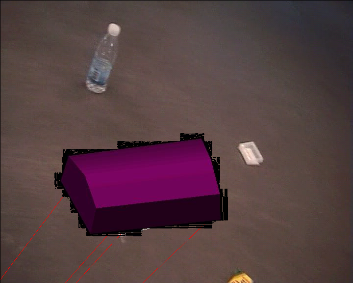
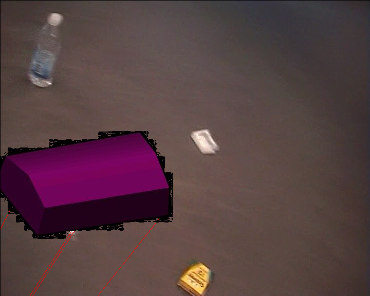
I've had some progress this past week. Different parts of the application were put together, giving a result where you can put a 3D model on top of an object (or on the ground, a wall etc.) in a background image.


The house/box was made in 3Ds Max, and is of course supposed to have the same orientation as the ground in the background, and look like it's placed on top of four dots on the ground, with appropriate size. The red lines below the box/house are supposed to continue in the same directions as the house wall corners - which they are obviously not, even though close for now. The red lines in the image under the house/box are supposed to go from the house corners to the third vanishing point - meaning that the house is a bit off, but not extreme. I'm guessing that it has something to do with the intrinsic camera parameter estimation, but I also know that there's some problems with making those parameters fit with Managed DirectX, since they are not of the same type....

I basically started again from nothing at the start of last week, worked 6-10 hours a day and came up with this. It's great progress for just a week. This week I'll make a new part of the program, after "resting" from it (actually doing my study job) for two days. The new part will be a camera calibrator, where a user can click a few times on an image, write some measurements, and then get the camera parameters for it.

Sunday, May 07, 2006

OpenCV stuff

I've started learning how to use OpenCV over the last few days. That's the Open Source Computer Vision Library. While learning some of it, I've been using my thesis partners code to get my hands dirty a bit faster. The problem with this approach is of course that you don't have full control of all parts, and there's always something there to supprise you. At the same time, when you're trying to avoid unpleasant suprises, you might end up making a mistake because of that. So I just spent 1-2 hours trying to figure out why nothing was drawn in the images/frames in the video. The fix: put the line-drawing before rendering the frame ;)

What I'll be doing this week is something like the following
  1. Calculate and draw the normals in the corners of the tracked building. Here I'll use the camera calibration matrix K together with the vanishing line (the "horizon") to find the third vanishing point.
  2. Calculate extrinsic parameters (position and orientation) in 4-5 frames, using the tracked building corners.

Thursday, April 13, 2006

Chosen First design method - Videotracking and mesh insertion

Just to clarify how the application is supposed to work, I'll give a summary here.

First, in my thesis partners part, coordinates in a video are chosen. This coordinates should at this early stage be the four corners of where a building should be inserted upon. Coordinates are found in a few frames, clicked on, and then the application interpolates between the frames. This is sometimes called keyframing.

My part of the application takes the four coordinates for the current frame, creates a homography matrix (used for calculating coordinate correspondence between different coordinate systems) and uses the homography to:
  1. Set texture coordinates for the ground plane - basically calculating the corner coordinates and then normalizing them.
  2. Find the position of where the house should be inserted on top of the ground plane.
  3. Find the rotation of the house, through the recieved four coordinates.
This sounds very simple in some ways, but there are some stumbling blocks - as has been described in previous posts. Currently, the greatest obstacle is that the video texture doesn't dispose - but I expect to have that solved within a few days (I'm also working on other stuff parallell, I'm not that slow ;p).

I expect to later move a lot of the calculations to HLSL, hopefully making it faster in the process. But for now I've decided to stick to the simplest ways of doing things and just make them work...


If we have time for the second method, it will be different in a number of ways. In that method we wont use any video in the 3D world, but instead only calculate which position and orientation to put the inserted building. While in the first method we can consider the building only being rotated around the Y-axis (meaning the building is always having the same sides facing up/down, but "changing other directions"), the second method also considers the other axises, making us calculate orientation and position in X, Y and Z coordinates. As a comparison, the first method calculates the position in X and Z coordinates, and as mentioned the rotation is only around the Y axis.

Wednesday, April 12, 2006

MDX Video texture code

Since I've found that a lot of people have had trouble with creating video textures with Managed DirectX, I decided to post some of the code for it here. The code basically loads the video and then renders when the current frame has been copied.

The following can be put for example where you create the mesh, as I did - or of course where ever else you find suitable:
video = Video.FromFile("test.avi"); //I'll set this to open a video with the file menu later
video.TextureReadyToRender += new TextureRenderEventHandler(onTextureReadyToRender); //Set an event handler to fire when the texture is ready to render.
video.RenderToTexture(_device); // Render the texture with the device (graphics card)
video.Play();
About an hour after writing the post it's time to update it.... I changed some stuff in the eventhandler, giving the following code as result:
public void onTextureReadyToRender(object sender, TextureRenderEventArgs e)
{

if (e.Texture == null)//If there's no texture file (video) for 'e', then get out of here
return;
SurfaceDescription ds = e.Texture.GetLevelDescription(0);
if (ds.Pool == Pool.Default)
{
sysSurf = _device.CreateOffscreenPlainSurface(ds.Width, ds.Height,
ds.Format, Pool.SystemMemory);
}
using (Surface vidSurf = e.Texture.GetSurfaceLevel(0))
{
if (_tex == null)//If there is no texture set to "_tex"
{
_tex = new Texture(_device, ds.Width, ds.Height,
1, Usage.Dynamic, ds.Format, ds.Pool);
}
using (Surface texSurf = _tex.GetSurfaceLevel(0))
{
SurfaceLoader.FromSurface(texSurf, vidSurf, Filter.Linear, unchecked((int)0xffffffff));
}
}
Invalidate();
}

To give some quick comments:
  • The update peoblem (application not updating without user interaction) was fixed when I put in the Invalidate() method.
  • The updating looks quicker than before - but of course it's impossible to tell by the naked eye.
  • The changes were made after I found some useful things in the book("Managed DirectX 9 Kick Start" by Tom Miller in the MDX team)
I believe most is pretty obvious. Just get the video file, check when it's loaded and ready to render, render it to a texture and watch the result...

Sorry about the lack of indents in the code - Blogger doesn't like the easy methods to create indents like tab/space, so I'll just skip that unless I get comments about it ;-)

I still have a lot of trouble with disposing the video texture when closing the application, but since I can't find anything to fix it after trying different ways and searching different places, I'll leave it for now...

The next things I'll do will just be minor issues. like for example stretching the video texture different ways, just to see the effect of it, and if it can be used easy and quick to rectify the frame images..

Tuesday, April 11, 2006

Video perspective distortion rectification

Well... the title says it all - need I say more?

This Thursday - two days away - I need to have the next step of the MDX application ready!! This means, at least, the following substeps, since my last post:
  • Creating a ground plane (a quad in Managed DirectX), which uses a video as texture. This substep was finished today, after a lot of trouble - mostly because there's next to no information about video textures with Managed DirectX. I almost gave up and changed to OpenGL, but since I want to learn as much MDX as possible I let it take the time it took.
  • Creating a new house mesh, which has the same size (at least proportions) as the place in the video, and a texture of its own.
  • Finding the homography (coordinate correspondences) between "real world coordinates" and the current frame in the video texture. This means calculating a new homography matrix for each frame, which of course may slow down the application. This can hopefully later be moved to HLSL instead, to let the graphics hardware take care of it whichever way it likes.
  • Setting texture coordinates of ground plane, according to the homography matrix.
  • Setting location and orientation of the house mesh, according to coordinates from the video texture, combined with the homography. However, the coordinates come from clicks in my thesis partners application, meaning I'll have to wait for those before doing anything final.
  • Fixing a lot of smaller and bigger issues (same texture showing on house and ground, video texture not updating without user input, application not completely stopping/disposing all when closing window etc.).
Future TODO's include
  • Doing all matrix calculations in graphics hardware - hopefully speeding the application up considerably.
  • Rendering the result and creating a "de-rectification" on the rendered video.
  • Obviously, clean up and comment the code more :-)

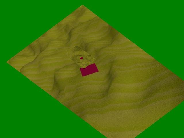
The image shows a sample frame of the latest version. The house mesh is positioned on top of the red square, but with the same texture as the ground plane.

As has been previously described, the ground plane will be changed to make the red square completely straight (perspective distortion rectification) in the current frame. This will give the effect of the image sides becoming crooked, while giving the opportunity to easier place the house on top pf the ground plane. The house will then, obviously, be placed with location and orientation according to the square.

Tuesday, March 21, 2006

2D to 3D and back...

So the last few posts have mostly been about DirectX, while I've been playing around with that. Now I've created an interface for importing a mesh (3D object/model) and set/change it's rotation, position and scale while also being able to change some camera parameters. The app also saves an jpg image which can be used on top of the video background to combine the both.

This is all great and basically what I need from Managed DirectX, so I won't revisit that for a few days. What I will do fr a while now includes research on how to find the right angle and position of the 3D object, with regards to the background movement and position of tracked objects in the background video. The translation between the image reference frame and the 3D world reference frame is usually done using Camera Parameters. These parameters can be divided into:
  • Extrinsic parameters such as rotation and translation (position) which gives us a matrix to perform transformation between world and camera reference frames.
  • Intrinsic parameters like focal length and the principal point (also the skew/distorion, which is often 0 in modern cameras). These parameters are part of a matrix which helps us perform transformations between the camera and image reference frames.
For example the image point (x,y,1) would be transformed from the world coordinate by doing the calculation M(int)M(ext)(X,Y,Z,1) (which is not completely correct written considering there's no scientific notation in blogger). I will dive deeper into each of the parameters later. For now, it's enough to say that the Camera Parameters can hopefully be retrieved through Camera Calibration.

Monday, March 06, 2006

Managed DirectX Tutorials

Since I'm just starting with MDX, I had to take some beginner tutorials in the subject. Most of those tutorials require some prior knowledge in C#, but considering this they are mostly well created and easy to follow. My three favorite beginner MDX tutorials are:
I believe all three work with the February DirectX SDK, even though I haven't completed all of them. Even though these take you a bit on the way, I believe getting a book is necessary sooner or later - but more on that another time.

Regarding my thesis project, it has been going slowly forward. I now have a simple MDX application to build on. I will continue by finding out how to do image rectification before texturing the ground plane. This will be followed by inserting 3D models of houses on top of the ground plane, hopefully giving a realistic look. Of course, the models have to be scaled and rotated according to coordinates on the ground plane - but that shouldn't be too hard once the images/frames from the video feed have been rectified.

Obviously, image rectification doesn't only lead to the possibility of inserting 3D models, but also ta actually create a 3D model of the ground plane itself, if enough information can be extracted from the original video.